
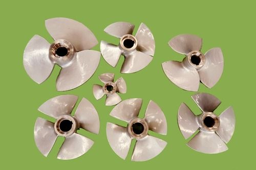

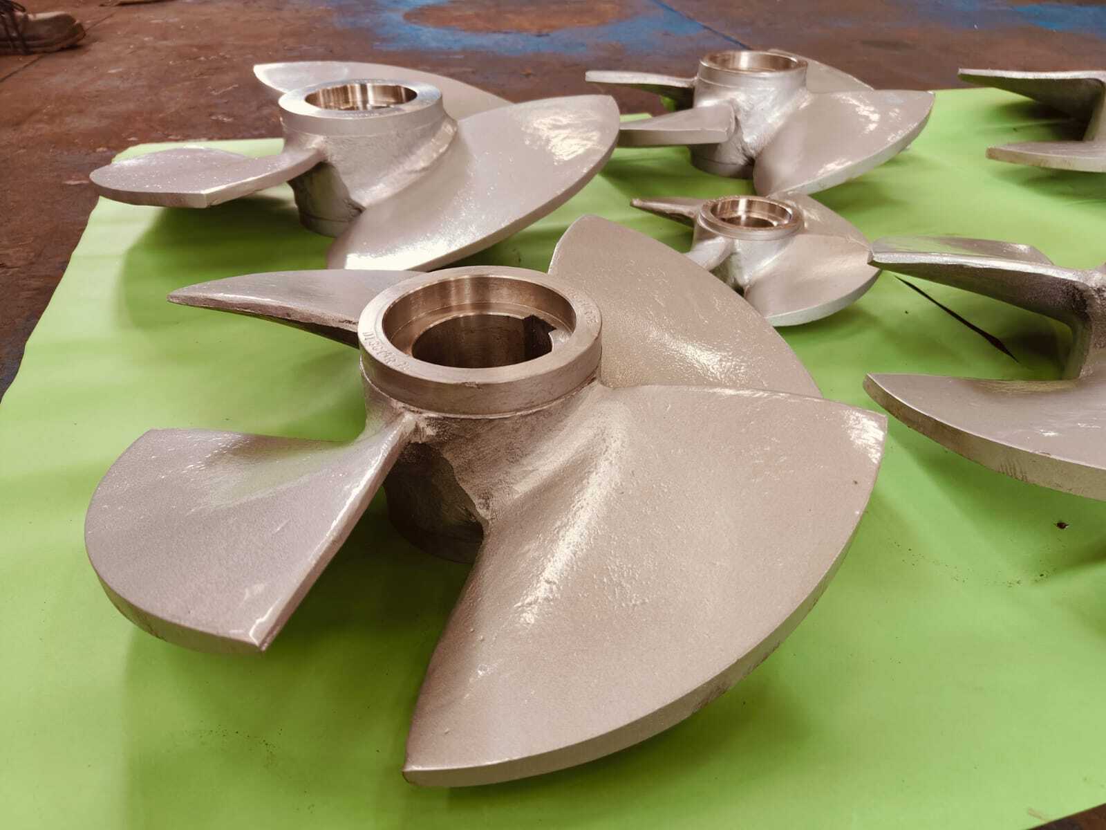
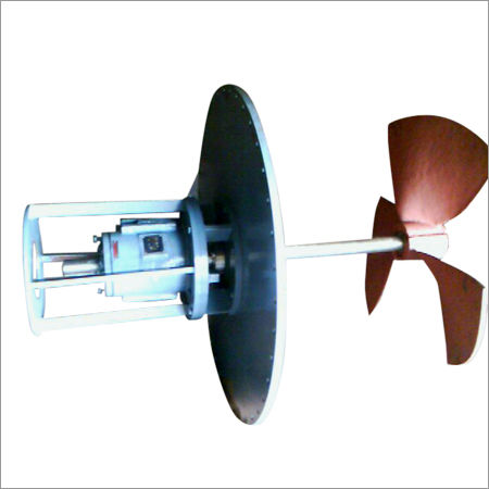
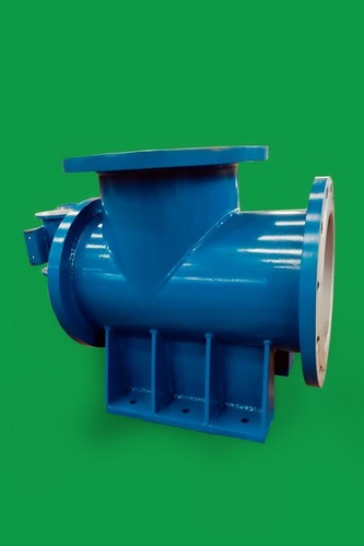
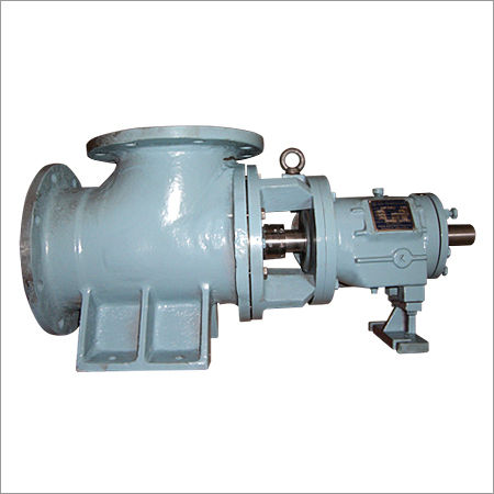
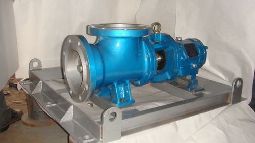
Propeller of Axial Flow Pump
25000 INR/Unit
Product Details:
- Head Size Low Head (2-20 meter)
- Inlet/Outlet As per Pump Design
- Theory Axial Flow Principle
- Flow Rate Up to 20000 m/h (when assembled in pump)
- Control System Not Applicable (mechanical part)
- Discharge Pressure Typically up to 2 bar (as part of pump)
- Working Temperature -10to 80 Celsius (oC)
- Click to View more
X
Propeller of Axial Flow Pump Price And Quantity
- 25000 INR/Unit
- 1 Unit
- 25000.00 - 100000.00 INR/Unit
- ISO G6.3 or better for vibration minimization
- Varies per size and material (typically 10 kg to 500 kg)
- Polished/Coated for corrosion resistance
- Epoxy or special coating optional
- Clockwise/Counterclockwise per configuration
- Precision casting/CNC machining
- Custom as per pump shaft size
- Hydrodynamically optimized (enables high efficiency)
- 3 to 6 blades (custom built)
Propeller of Axial Flow Pump Product Specifications
- As per Pump Design
- Other
- Low Head (2-20 meter)
- Not Applicable (propeller part only)
- Axial Flow Propeller (Three/Four Blade Customization)
- As per Pump Assembly (customizable)
- Axial Flow Pump Component
- Axial Suction (through propeller axis)
- Axial Flow Principle
- High-grade Stainless Steel/Bronze/Aluminum Alloy
- Other
- Customizable (common: 150mm - 1600mm)
- Keyed/Bushed to Pump Shaft
- Typically up to 2 bar (as part of pump)
- Up to 1450 RPM
- -10to 80 Celsius (oC)
- Up to 20000 m/h (when assembled in pump)
- Not Applicable (mechanical part)
- Low Pressure Application
- Dependent on Pump Motor (does not apply to propeller only)
- IS/ISO/DIN Standards Applicable
- Depends on Pump Configuration
- High strength, corrosion-resistant, dynamically balanced blades, customizable dimensions
- ISO G6.3 or better for vibration minimization
- Varies per size and material (typically 10 kg to 500 kg)
- Polished/Coated for corrosion resistance
- Epoxy or special coating optional
- Clockwise/Counterclockwise per configuration
- Precision casting/CNC machining
- Custom as per pump shaft size
- Hydrodynamically optimized (enables high efficiency)
- 3 to 6 blades (custom built)
Product Description
Designing the aerofoil shape of a propeller is critical forachieving efficient propulsion in applications such as aviation, marine, andwind turbines. The aerofoil shape directly impacts the thrust generated, fuelefficiency, noise levels, and overall performance. Heres a breakdown of thekey considerations in designing a propeller aerofoil:
Key Considerations in Propeller Aerofoil Design:
Lift and Drag Characteristics:
Lift: The aerofoil must generate sufficient lift to propelthe vehicle forward. The lift coefficient
C
L
should be maximizedwhile maintaining low drag.
Drag: The drag coefficient
C
D
should be minimizedto ensure efficient operation, as excessive drag reduces the propellersefficiency.
Angle of Attack (AoA):
The AoA is the angle between the chord line of the aerofoiland the direction of the oncoming air. The design must optimize the AoA tobalance lift and drag across the entire length of the blade.
The AoA typically varies along the blades span, beinghigher at the root and decreasing towards the tip to maintain consistentperformance.
Twist Distribution:
Propeller blades are twisted from root to tip to ensure thateach section of the blade operates at its optimal AoA.
The twist is necessary because the relative velocity of theblade increases from the hub to the tip, which would otherwise cause the outersections of the blade to stall if the twist were not present.
Thickness Distribution:
The thickness of the aerofoil generally decreases from theroot to the tip. A thicker root provides structural strength, while a thinnertip reduces drag and improves aerodynamic efficiency.
The maximum thickness is typically located around 25-30% ofthe chord length from the leading edge.
Camber:
The camber refers to the curvature of the aerofoil. A highercamber can increase lift but also raises drag. The optimal camber is selected basedon the intended operating speed and Reynolds number.
Cambered aerofoils are commonly used for propellers thatoperate in subsonic regimes, while symmetrical aerofoils might be used in otherspecific applications.
Reynolds Number:
The Reynolds number, which depends on the blades chordlength, speed, and the viscosity of the air, affects the aerodynamiccharacteristics of the aerofoil. Designers often choose aerofoil shapes thatperform well across a range of Reynolds numbers.
Mach Number Effects:
For high-speed applications, especially in aviation, thedesign must account for compressibility effects as the blade tips may approachtransonic speeds. This can lead to shock waves and drag divergence, which needto be mitigated.
Structural Considerations:
The aerofoil shape must balance aerodynamic performance withstructural integrity. The aerofoil should be strong enough to withstand thecentrifugal forces and aerodynamic loads during operation.
Materials:
Material selection plays a role in the aerofoil design.Composite materials allow for more complex shapes and better weightdistribution, but the design must consider the materials properties such asstiffness and fatigue resistance.
Aerofoil Shape Design Process:
Preliminary Design:
Start by selecting a base aerofoil shape from standardaerofoil series (e.g., NACA, Clark Y) that meets the general requirements forlift, drag, and operational speed range.
Use empirical data and existing performance charts to narrowdown the initial design.
Aerodynamic Analysis:
Perform computational fluid dynamics (CFD) simulations toanalyze the airflow around the aerofoil and optimize the shape for specificperformance criteria.
Examine the lift-to-drag ratio (
/
C
L
/C
D
) across different sectionsof the blade.
Optimization:
Optimize the twist and chord distribution along the blade.This step may involve iterative testing and adjustment of the aerofoil shapeand blade geometry.
Consider multi-objective optimization techniques to balanceconflicting performance requirements (e.g., maximizing thrust while minimizingnoise).
Prototyping and Testing:
Manufacture a prototype blade with the designed aerofoilshape and test it in a wind tunnel or on a test stand.
Validate the design under operational conditions and adjustas necessary based on test data.
Final Design Adjustments:
Refine the design based on testing results, including anynecessary adjustments to the aerofoil shape, twist, or materials to improveperformance and durability.
Key Aerofoil Series for Propeller Design:
NACA Series: The NACA 4-digit and 5-digit series are oftenused for their well-documented performance characteristics. The NACA 16-seriesis particularly favored for high-speed propellers.
Clark Y: A widely used aerofoil with good liftcharacteristics and moderate drag, often chosen for low to moderate speedapplications.
Laminar Flow Aerofoils: Modern propeller designs might uselaminar flow aerofoils that maintain a smooth flow over a large portion of theblade to reduce drag.
Designing a propeller aerofoil is a complex process thatinvolves balancing aerodynamic performance with structural requirements andmaterial constraints. Advanced simulation tools and testing methods areessential to refining the design and ensuring that it meets the specific needsof the application.
Hydrodynamic Blade Design for High Efficiency
Our propeller blades are optimized for hydrodynamic performance, minimizing resistance and maximizing flow rate. Engineered with advanced design techniques, each blade enables smooth water passage, reducing energy consumption and improving overall pump performance. The blade count and profile are fully customizable, ensuring the ideal match for your application.
Precision Manufacturing and Corrosion Resistance
Every propeller is manufactured by precision casting or CNC machining and finished to achieve optimal strength and surface quality. Polished or specially coated surfaces provide excellent resistance to corrosion, ensuring a long operational life even in harsh water or marine conditions. Optional epoxy coatings are available for projects requiring even greater protection.
Custom Fit for Industrial Applications
Designed to integrate seamlessly with various pump assemblies, our propellers feature custom shaft bores and are dynamically balanced to ISO G6.3 or better for minimal vibration. Sizes, weights, and finishes can be adapted to your specifications, making them suitable for waterworks, flood control, circulation systems, and other industrial or municipal uses.
FAQs of Propeller of Axial Flow Pump:
Q: How is the rotation direction of the propeller determined?
A: The rotation direction (clockwise or counterclockwise) is specified during configuration to match the pumps assembly design. This ensures optimal flow and compatibility with the rest of the pumping system.Q: What benefits does a hydrodynamically optimized blade profile offer?
A: A hydrodynamically optimized blade profile minimizes drag, boosts efficiency, and enables the pump to deliver higher flow rates with lower energy consumption. This translates to significant operational cost savings.Q: When should I choose a coated or polished surface finish for the propeller?
A: Coated or polished finishes are recommended when the propeller will be exposed to corrosive environments, such as seawater or aggressive industrial fluids. Epoxy or special coatings further enhance resistance to corrosion and extend service life.Q: Where are these propellers typically used?
A: These propellers are found in axial flow pumps deployed for water supply, drainage, flood control, circulation systems, irrigation, and marine applications where high flow and low head conditions are required.Q: How is the propeller customized to fit my pump assembly?
A: Propellers are custom-built to match your pumps shaft size, blade count, and dimension requirements. Caliber (diameter), shaft bore, and mounting type (keyed/bushed) are each tailored as per your provided specifications.Q: What is the manufacturing process for these propellers?
A: Depending on requirements, propellers are produced by high-precision casting or CNC machining, providing a combination of structural strength and smooth surface finish. Strict balancing procedures (ISO G6.3 or better) are followed to minimize vibrations during operation.Q: What are the main advantages of using a dynamically balanced propeller?
A: Dynamically balanced propellers reduce vibrations, protect pump bearings, and minimize mechanical noise. This leads to more reliable, silent pump operation and extended equipment lifespan.Tell us about your requirement

Price:
Quantity
Select Unit
- 50
- 100
- 200
- 250
- 500
- 1000+
Additional detail
Mobile number
Email

Other Products in 'Axial Flow Pumps' category
RAS PUMPS PVT. LTD.
GST : 27AAFCR8277A1Z9
GST : 27AAFCR8277A1Z9
- A-142, MIDC, Phase 1 Kalyan shil Road, Near plus, Vicoo, Dombivli - 421203, Maharashtra, India
- Phone : 08045802815
- Mr Amol Yeole (Director)
- Mobile : 08045802815
-
 info@raspumps.com
- Mr Amol Yeole (Director)
Mobile :+919594448444

RAS PUMPS
All Rights Reserved.(Terms of Use)
Developed and Managed by Infocom Network Private Limited.
Developed and Managed by Infocom Network Private Limited.

